

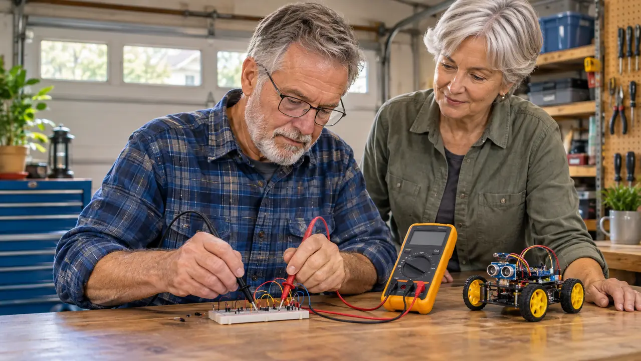
The first time an ELEGOO robot car build of mine sat on the garage floor and refused to move, I did what most beginners do: I started swapping parts. I checked the battery, then the switch, then the code. Ten minutes later I found the real problem. I had plugged one sensor cable into the wrong port. No part was damaged. Nothing needed replacing. The car was fine and my troubleshooting order was not. That was February 2025, and it is the reason I keep an AstroAI AM33D within arm's reach on the bench. Two simple checks, continuity and DC voltage, would have sent me to the connector first instead of the code.
I spent 34 years as an aircraft avionics technician before I retired in November 2023. At the hangar I used work-issued shop meters. I never owned a multimeter until I bought the AstroAI in February 2024, a few months into hobby builds. Since then it has been the meter I reach for on breadboard rails, battery packs, jumper wires and the 5V and 3.3V pins on my ELEGOO UNO. This is the process I use. It is not a lab procedure. It is a bench procedure for low-voltage hobby work, and it assumes you will keep the meter away from household mains wiring. I do.
Find the Bad Connection Before You Swap Another Part
The AstroAI AM33D is the meter on my bench for continuity and DC voltage checks on hobby builds. It reads the 5V and 3.3V rails, checks a jumper end to end, and fits in the same drawer as the test leads.
Amazon Check the AstroAI AM33D on Amazon →The Five Steps I Use
Step 1: Set the meter up before you touch the build
Start with the meter off and the build unplugged. Plug the test leads into the meter the way the included manual shows for voltage and resistance. The AstroAI ships with the meter, a 9V battery, two test leads and a user manual. If the display is faint or the low battery indicator comes on, replace the 9V before you trust a reading. I replaced mine once, in spring 2026, after about two years of use.
Select the DC voltage function for voltage checks. Select continuity for the wire checks. Touch the two probe tips together and confirm the meter responds with a short. If it does not, check the leads first. A bad lead will make every circuit look bad. Keep the meter on a dry bench, not on the concrete floor, and keep your fingers behind the probe tips. The meter is listed to 500 volts maximum, with an operating temperature range of 32 to 104 °F. That 500 volt rating is not a reason to open a wall outlet. I do not use this meter on household mains.
On the AM33D the jacks are labeled and the leads only fit one way, but I still look at them every session. One evening I moved the robot car across the bench, the black lead worked loose at the jack, and I spent a few minutes reading a supply that was not connected to anything. I could not see it, because the plug was still sitting in the hole. Now the last thing I do before a reading is push both plugs down firmly and touch the tips together again. It costs two seconds, and it has kept me from writing a bad number into the notebook more than once.
Step 2: Run continuity with the power off
Continuity is a resistance check with a simple answer: is there a complete path between these two points? The build must be unplugged and the battery removed. On the ELEGOO car, I pull the battery holder before I check any cable. Then I put one probe on each end of the suspected path. A good jumper wire or a closed switch reads near zero. An open cable reads the same as holding the probes in the air.
Test the path, not just the part. On the robot car, that means one probe on the sensor plug pin and the other on the matching header pin at the board. Wiggle the cable while you watch the reading. A number that jumps around is an intermittent connection, and that is worse than a clean open because it will work on the bench and fail on the floor. If the path is good, the cable is not your problem. Move to the next connection and leave the soldering iron alone.
Continuity also catches the mistakes you cannot see. I check every jumper before it goes into a breadboard. I check the header pins on the ELEGOO UNO after I have moved the board around. The one part I did kill, an LED I wired without its resistor in May 2024, reads open on a diode check. That was my mistake, not the meter's. The lesson was cheap and I have not repeated it.
Here is a concrete one from my bench. In the fall of 2025 I had a jumper that looked perfect and read open only when I bent it near the insulation. Straight, it showed a short. Bent, the display went back to the open reading. The copper inside had broken and the plastic was holding the two ends close enough to fool a visual check. That is exactly the fault continuity finds and eyesight does not. I swapped in a fresh wire and the sensor started reporting again. Since then I flex every suspect jumper while the probes are on it.
Step 3: Read DC voltage from ground up
DC voltage checks are done with the build powered. Put the black probe on circuit ground. On the ELEGOO UNO, that is a GND pin. On the robot car, use the battery negative terminal or the board ground the diagram shows. Put the red probe on the point you want to test. Read the display. Start at the source and work toward the load.
First check the battery or the USB supply at the input. Then check the regulator output. On a USB-powered UNO, the 5V pin should read close to 5 volts. The 3.3V pin should read close to 3.3 volts. I do not expect a perfect number. I expect a number that is close and steady. If the 5V rail reads 4.6 volts and the board is behaving strangely, that is a clue. If it reads 0 volts, stop and find out why before you plug in another sensor.
The AstroAI is a 2000 count meter with a backlit LCD and a sampling speed of two times per second. That is enough resolution for hobby rails and battery packs. It is not a lab meter, and the listing says it cannot test all AC current or AC voltage below 100 mV. For this work, DC volts and continuity, that limitation does not get in the way. Keep the probe tips apart. A slip between 5V and ground will shut down the board or kill a part.
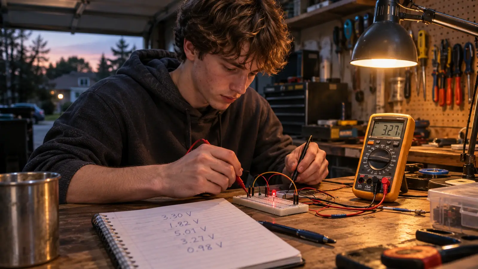
One cold morning in the garage I read the 5V rail on the UNO at 4.7 volts, and the board kept resetting every time a small servo moved. Nothing was wrong with the sketch. The old USB port on the laptop was not keeping up with the current draw. I moved the cable to a powered hub, the same pin read 4.95 volts, and the resets stopped. Both numbers went into the notebook side by side, 4.7 and 4.95, because that pair is the whole lesson. The rail tells you the story before the code does.
Step 4: Chase a dead build in a fixed order
When the ELEGOO car did not move on its first Saturday, the order I should have used was: battery, switch, cable, sensor, code. I went to code too early. Now I start with the battery under load. A 9V or AA pack can read fine with no load and sag when the motors ask for current. Then I check the switch with continuity, power off. Then I check each sensor cable end to end. Only after those three checks do I power the board and read DC volts at the 5V rail.
If the rail is good and the cable is good, the problem is likely the sensor or the code. That is the point to open the serial monitor and read what the board thinks it sees. On my car, the sensor cable was in the wrong port. Continuity would have shown the cable was fine, and the diagram would have shown the port was wrong. The meter does not replace the diagram. It tells you which page of the diagram to look at.
Battery sag is the check that fools people, so I do it out loud now. A fresh set of AA cells read about 6 volts across the pack with nothing running. Press the throttle in the app and that number dropped to roughly 4.6 while the motors pulled current, then climbed back when I let go. Some dip is normal. A pack that falls well below what the board needs will never drive the car no matter how clean the code is. I write the resting number and the loaded number both, one line apart, and that rules out the usual suspect before I open the sketch.
I keep a short list taped inside the bench drawer: battery, switch, cable, rail, code. It is not a fancy flowchart. It is there so I do not start swapping parts at random. Random swapping is how beginners turn one problem into three.
Step 5: Write the readings down
Write the reading, not the word good. A notebook line that says '5V rail good' tells you nothing six months later. A line that says '5V rail 4.98, 3.3 rail 3.29, battery 8.9, all steady' gives you a baseline. When the same board acts up in November, you can compare. My bench notebook has dates, the board, the test point and the number. It takes thirty seconds and it has saved me from chasing a problem that was really just a low battery.
Record the temperature if the garage is cold. The meter is rated for 32 to 104 °F, and I do not ask it to work outside that. I also note which leads I used. A set of test leads can fail, and a reading that makes no sense is sometimes the lead, not the board. Touch the leads together, confirm the short, then go back to the test point.
After a build is working, I take one final set of readings and leave them in the notebook. That is the reference. If the robot car starts steering wide or the UNO resets when a motor kicks on, I check the reference before I check the code. More than once the answer has been a tired battery, not a software bug.
My first ELEGOO car sat dead for ten minutes because one sensor cable was in the wrong port. Continuity and a DC voltage reading would have found it in two.
What Else Helps
Good light helps more than most people expect. My bench has a magnifier lamp, and I use it when I am reading header labels. A printed pinout for the board is also worth the paper. So is a known-good battery and a spare set of test leads. The AstroAI came with one set of leads, and they have held up, but I check them against each other before I blame a circuit.
Keep the meter away from mains wiring and from any circuit that has a charged capacitor. This article is about low-voltage hobby builds, not household repairs. If a build uses a wall adapter, unplug it before continuity checks. If you are not sure whether a point is live, treat it as live and stop. The meter is a tool for answering a question you have already made safe to ask.
Two Checks, One Meter, Fewer Swapped Parts
The AstroAI AM33D has been on my bench since February 2024. It is the meter I use for continuity on cables and DC voltage on battery packs and 5V rails. If you are building the ELEGOO car or learning on a breadboard, these are the two checks you will use most.
Amazon See the AstroAI AM33D on Amazon →