
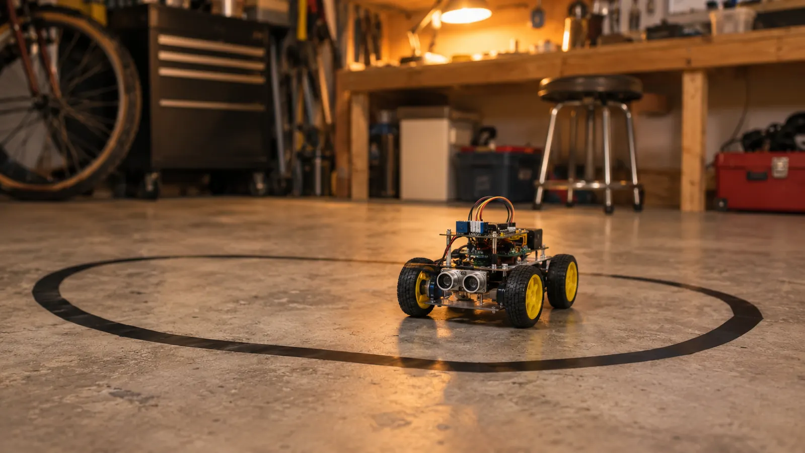
The first time I set my ELEGOO robot car down on the tape loop, it went about eight inches, twitched left, and drove off the line like the tape had said something rude about its mother. I had spent two Saturdays on the build, six hours or so at the garage bench, and the part everyone warns you about, the wiring, went fine. The part nobody warns you about is the line tracking, and that is where an afternoon disappears if you let it.
Here is what I wish somebody had told me before I started poking at the sketch. Line tracking is not a software problem first. It is a measurement problem. The car does not see a line. It shines light at the floor, reads how much comes back, compares that number to a threshold somebody picked, and steers on the answer. When it wanders off the tape, the fix is almost always in that comparison, not in a new library. My ELEGOO UNO R3 Smart Robot Car Kit V4 has been running the same loop of black electrical tape on my garage concrete for a year and nine months now, and the calibration I landed on took one afternoon and has not needed touching since.
The tutorial ships in the box. The calibration takes an afternoon.
The V4 kit came with the camera, an illustrated tutorial and example programs that already do the heavy lifting. You are not writing a line follower from scratch, you are tuning one.
Amazon See the ELEGOO Smart Robot Car Kit V4 on Amazon →Step 1: Build the track before you touch a single line of code
The module under the front of the car shines light down at the floor and reads what bounces back. Black tape swallows most of it. Light concrete throws most of it back. That difference is the entire signal, which means your floor and your tape are half the calibration whether you like it or not. Get the track wrong and no threshold will save you.
My loop is black electrical tape laid on bare garage concrete. Three things matter. Matte, not glossy, because shiny tape throws a hard glint straight back at the sensor and the reading goes strange at certain angles. Flat, not wrinkled, because a lifted tape edge becomes a little ramp the front wheels climb. And gentle, because my first loop had corners so tight the car could not physically turn fast enough to stay on them, which looks exactly like a calibration failure and is not one. I widened the corners until the car had room to correct, and three problems I had been blaming on code simply went away.
I marked my loop out in chalk before I pulled any tape, eight feet long and four feet wide, with the curves at each end drawn around an old coffee can so they matched. Then I laid the tape along the chalk. Twenty minutes on a Sunday afternoon in March 2025 and most of one roll. Doing the layout on the concrete in chalk first is worth the extra five minutes, because tape you have already pressed down is tape you will argue with later.
Sweep the concrete first. Grit changes the reading more than you would think, and a single dry leaf sitting on the loop will hand you fifteen minutes of chasing a bug that is not in your sketch.
Step 2: Check how the module sits and where its cable goes
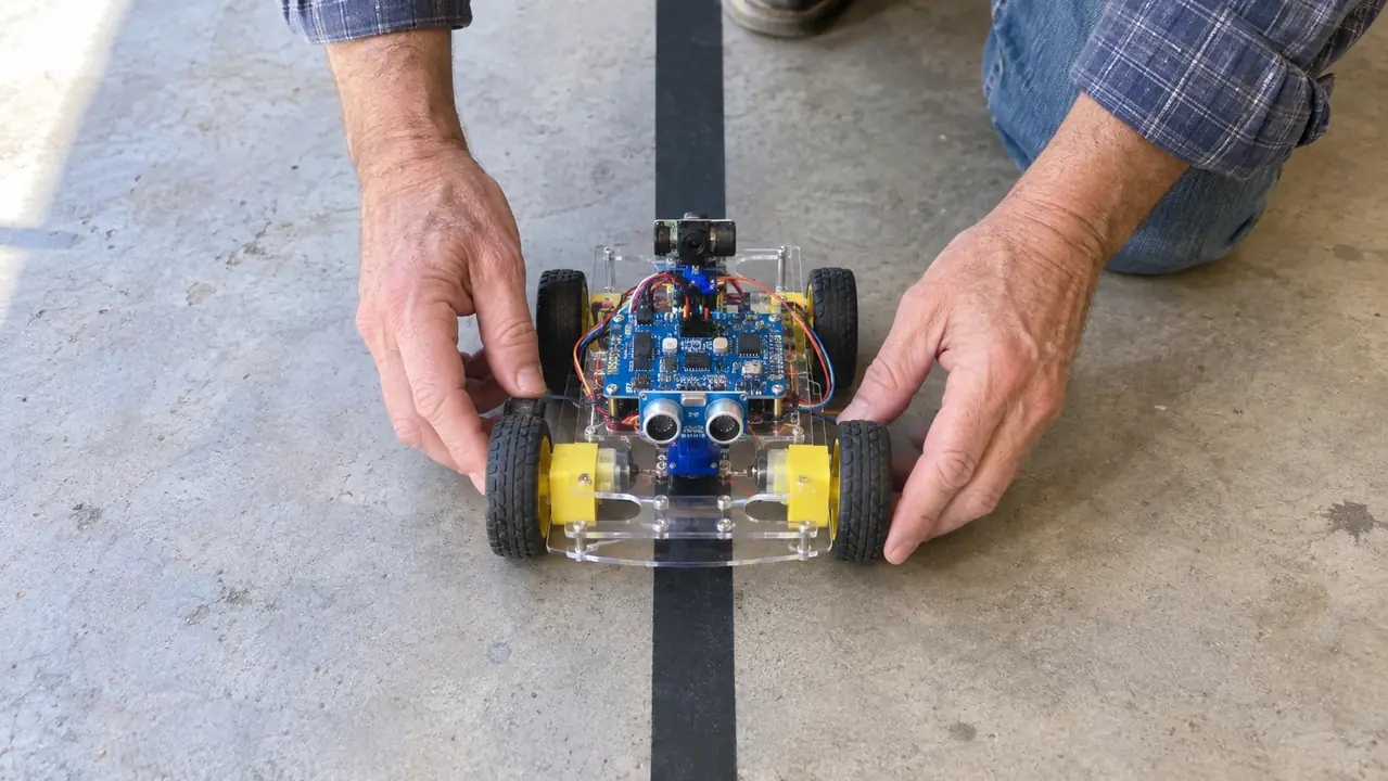
The module hangs under the front of the car, pointed at the floor. Two things go wrong here and both look like software. If it sits too high, the beam spreads and the sensor averages a wide patch of floor plus tape, so black and white start to look the same. If it sits too low it drags, catches the tape edge, and the car lurches at every seam. Mine sits close enough to read clearly and high enough that nothing touches.
I checked the gap the crude way, with a folded business card. Slid one under the front edge and watched the readings, then two, then three. At one card the number barely moved between white card stock and black tape. At three the margin got thin enough that a bright morning could push it over the threshold. That was more use to me than any height figure, because it was my floor and my tape in my garage, not a number off a forum.
Then the cable. The kit uses keyed XH2.54 connectors, which stop you from plugging one in backwards, and that is a real improvement over the bare pin headers I fought for 34 years on aircraft harnesses. Keyed does not mean foolproof. On my first Saturday I had one sensor cable in the wrong port and the car simply did not respond. It took about ten minutes with the illustrated tutorial and the board diagram to find it. No damage, no drama, just ten minutes of me assuming the code was broken when the code was fine.
While you are down there, prop the car so the wheels are off the floor. You want to watch the readings change as you slide a card under the module, and you cannot do that while it is driving away from you.
Step 3: Read the numbers instead of guessing
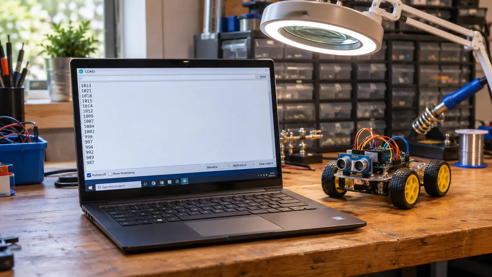
This is the step people skip, and it is the one that ends the guessing. Load an example program that prints the tracking readings to the Serial Monitor, open the monitor on your laptop, and watch the numbers. Slide a piece of white card stock under the module and note what you see. Then slide a scrap of the same black tape under it and note that.
Write both numbers down. That is your whole calibration, in two columns. If white reads far from black you have margin and the car will be reliable. If they sit within a few counts of each other, you have found your problem, and no amount of clever steering logic fixes a signal that thin. The fix is almost always mechanical. Lower the module a touch. Get the tape flatter. Move the car off the glossy patch of floor.
I did this on a Sunday afternoon in March 2025 and wrote both numbers in pencil on the corner of the tutorial page, which is still folded in the kit box. The first pass was a mess. I had the garage door up and the noon light coming across the concrete, and the readings wandered every time a cloud crossed the sun. I closed the door, ran the same test again, and the numbers sat still. That was the whole bug. Not the sketch, not the module, just a hundred square feet of daylight bouncing off a floor.
Watch for flicker while you are in there. A steady number is trustworthy. A number that jumps around while nothing moves is telling you light is getting in from somewhere, and it is worth finding the somewhere before you go blaming the sketch. Run the card under the module three or four times, slowly, and see whether it gives you the same pair of numbers each pass.
Two numbers on a scrap of paper, one for white floor and one for black tape, told me more about why the car wandered than an hour of reading other people's sketches.
Step 4: Put the threshold in the sketch and work out which way is which
Open the tracking example and find the value it compares the reading against. Put your own number in as a named constant at the top of the sketch, roughly halfway between your white reading and your black reading, and start there. Halfway is a starting point, not a law. If your readings are noisy, bias the threshold toward the black number so the car errs toward saying it is on the line rather than off it.
Then check direction, with the wheels still up off the bench. A car that steers away from the tape instead of toward it will look broken and is not. It is inverted, which is a one character fix once you know. Label the sensors. I keep a strip of masking tape on the underside with L and R written on it in marker, because I have talked myself out of which side is which more times than I care to admit for a man with my background.
Upload, set the car down facing along the tape, and let it run two feet. If it corrects and settles, you are close. If it wiggle-waggles left and right down the middle of the line, your threshold is fine and your steering correction is too aggressive. That is a different problem and it belongs in the next step.
Step 5: Slow it down, then test it like you mean it
Speed is the enemy of a clean line follower. A car that crosses the whole loop in four seconds has almost no time to see the tape and correct before it is off it again. Drop the drive speed until watching it is nearly boring. Once it tracks reliably at a crawl, raise it in small steps and find the point where it starts to lose the line. That point is your real limit, and it is usually lower than you want it to be.
Then run laps and count. I keep a tally on the corner of the garage whiteboard: twenty laps at the crawl, then twenty more one notch faster, with a note of where it drops the line. The faster set failed at the same corner on lap seven, then again on lap eleven in exactly the same place, which told me the corner was too tight and not that the sensor was bad. Fix the track first and the code second. Most line tracking problems I have chased were physical problems wearing a software costume.
Last thing: test under the light you will actually run it in. My garage is dim in the evening and bright at noon with the door up, and those are two entirely different floors as far as the module is concerned. Run the loop in both. Once it survives both, take the ELEGOO app for a drive and let the car do something other than trace tape, because a kit that only ever does the tutorial is a kit that ends up on a shelf.
What Else Helps
Keep the floor clean and the tape pressed down. I keep a scrap of the same tape in the parts drawer so that when a corner lifts I patch it with identical material instead of whatever is nearest, because different tape is a different reading and you will chase that for an hour.
Check that the car is getting steady power. A supply that sags shows up as twitchy, inconsistent tracking that looks exactly like a bad threshold, and it will send you back into the sketch for no reason at all.
If your sketch also runs the obstacle avoidance behavior, turn it off while you calibrate the line follower. Two behaviors reacting to the same inputs at once make it impossible to tell which one turned the car.
And read the example programs before you replace them. The illustrated tutorial that ships with the kit walks through the examples in order, and the line tracking one is short enough to read in a few minutes. I spent 34 years reading wiring diagrams for a living and I still start with the documentation, because somebody has usually already solved the problem I am about to have. Carol walked out to the garage while the car was on its twentieth lap, watched it for a minute, and asked what it does. Fair question. It follows a line. The honest answer is that the line is not the point. The point is that you built something that reads its own surroundings and reacts, and you tuned it yourself with two numbers and a scrap of paper.
The tape loop is still on my garage floor
The V4 kit brought the camera, the illustrated tutorial and the example programs that got me to a working line follower. Everything after that was tape, light and two numbers I wrote down on a scrap of paper.
Amazon Check Today's Price on Amazon →